About paper
Czech originalA few things from the summer camp – this time on the topic: “What already the ancient Greeks knew … and do we know it too?”
This contribution describes seven of the 18 projects that were worked out by the participants of the Young physicists’ and mathematicians’ summer camp in Kořenov between 21 July and 4 August 2012. The names of described projects are: Heron’s inventions, Levitating motor, Pythagorean tuning, Radio for a castaway, Light communication, Wave of pendulums and Water integrator.
Introduction
The main part of the scientific training at the camp is participants’ own work on projects in which students (in two or three-member teams) under the guidance of tutors work out a chosen topic by themselves. They “defend” the progress of their work in front of a “committee” in the middle of the camp and present their results at the concluding conference.
The details about other parts of the training and leisure program can be found both on the web site of the camp [1] and in contributions to Inventions Fair in the previous years (e.g. [2])
Projects
The training program had a uniting theme “What already the Ancient Greeks knew” this year. A question in the subtitle asked whether we do know it too. The participants chose the following 18 projects from an offer of more than forty projects (projects set in bold are described below in more detail):
• Figurate numbers and livestock
• Photogrammetry
• Physics of psyche
• Heron’s inventions
• Cheops’ pyramid
• Pocket sundial
• Levitating motor
• Linear perspective
• Mathematic inventions
• Pythagorean tuning
• Pythagoras’ toys
• Firebug plays
• Radio for a castaway
• Light communication
• Wave of pendulums
• Water integrator
• Units sampler
• Golden section
The following descriptions of chosen projects are based on the documentation worked out by the participants. The complete documentation of some projects along with photos is available in Czech on the website of the summer camp [1].
Heron’s inventions
The project inspired by the work of the Hellenic inventor Heron of Alexandria, who lived in the first century AD, was elaborated by Kryštof Hes and Adam Tywoniak. Heron is the author of a range of inventions: automatic theatre, automatic crossbow, simple steam turbine and others. The project authors’ original intention was to build several models of Heron’s inventions and to describe their physical principles. Eventually, it turned out that the work on one occupied the authors completely and thus the goal was revised: to build and describe one chosen invention of the famous inventor; and this invention was the automatic opening of temple doors.
This mechanism might have functioned probably in this way: a crowd of believers gathered in front of the temple doors. The priest offered a burnt sacrifice on the altar in front of the temple and the massive temple doors opened after a moment. The believers were fascinated and deemed it the evidence of god’s presence and this was used by the priests to collect more money from the believers.
The operation of the mechanism is in fact based on heat expansion of air – the diagram is depicted in Fig. 1. Above a burner (1), air is heated in a closed vessel (2). With increasing temperature the air expands and is led by a tube (3) to a vessel (4). The caused overpressure pushes water out of the vessel through a tube (5) into a cup (6). The cup is hanging on a string that goes through a pulley system (7) and there is another cup (8) hanging on the other end of the string with a constant mass of water acting as a counterweight. As soon as there is enough water in the cup (6), the cup outweighs the counterweight and the movement of the string is transferred by pulleys to rotational movement of the door axes.
To close the doors again it is enough to put the vessel (2) aside from the heat source and wait for the vessel to cool down. The air in the system contracts back to its initial volume and the caused underpressure pumps the water from the cup (6) back to the vessel (4). The weight (8) starts moving down and the doors are closed again by the movement of the string.
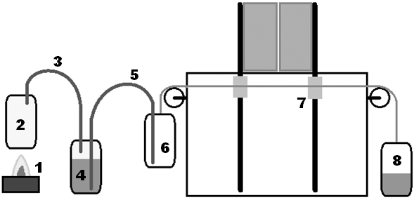
Fig. 1. Operation diagram of the Heron’s invention
After minor technical problems that were successfully solved, both authors completed a functional model.
Levitating motor
The goal of the project was to build an electromotor driven by the light energy. The construction was inspired by a video on the Internet (see [3]) but the design was based on studying properties of magnets and used photovoltaic cells. The core of the solution is a rotor that hovers in the magnetic field of fixed magnets of the stator. The project solvers Adéla Miklíková and Jan Stopka had built a few prototypes before reaching the final solution. The first construction is based on the use of ferrite magnets. A rotor made of an aluminium rod and two round ferrite magnets with central holes is hovering thanks to repulsion in the field of four cylindrical ferrite magnets. The magnets of both the rotor and the stator are oriented outwards with their north poles. This ways the rotor is stabilized sideways. To prevent motion along the axis, the magnets of the rotor are shifted relative to the stator to give rise to a force in the direction of the axis that is compensated by a support (see Fig. 2a)
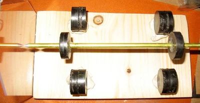
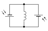
Fig. 2. a) Provisional research construction. b) Circuit diagram with photovoltaic cells and a coil.
This construction already enabled smooth prolonged rotation of the rotor by inertia thanks to minimal friction. Yet it was necessary to equip the rotor with a coil and photoelectric cells. The strength of force effects with used ferrite magnets was on the edge of needed parameters. Thence neodymium magnets were used in the final stage. The rotor moreover carries two perpendicular coils with about 100 turns each. Each coil is connected to a pair of photovoltaic cells as shown in the diagram in Fig. 2b. The photovoltaic cells have an area of 26 mm × 46 mm and give 0.5 V/100 mA in the sunlight.
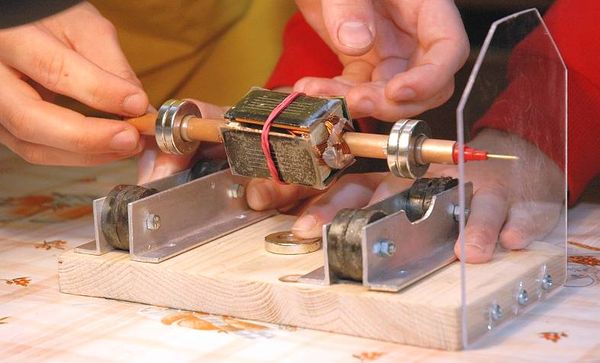
Fig. 3. Construction of the motor before finalization
The action of the motor is captured on a video on the website of the camp [1].
Pythagorean tuning
The aim of the project was to construct a single-string musical instrument that could be used to show the difference between the standard chamber tuning and the Pythagorean tuning. During the realization, the solvers of the project (Jan Hadrava, Martin Mirbauer and Jan Sixta) have expanded it with demonstration of using different types of sound sensors that are used with musical instruments nowadays and by a draft of a contactless input interface for PC that can read the position of a magnet in two directions and can be theoretically connected to any sound synthesizer.
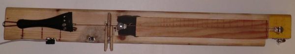
Fig. 4. “Completed musical instrument”.
A tailpiece, bridge, string and tuning mechanics from older instruments were used in construction of the instrument, everything else was manually fabricated. As for dimension, the instrument has length of the resonating string of 328 mm which responds by size to a full size violin. The sound is generated in a standard way with a bow.
The sound of the “violin” is recorded with three types of sensors: a) electromagnetic, b) piezoelectric, c) classical microphone. It can be switched between individual sensors with an in-built switch.
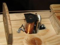
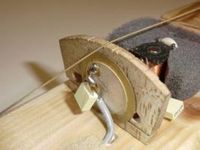
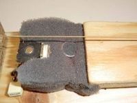
Fig. 5. a) electromagnetic pickup, b) piezoelectric pickup, c) classical microphone
A copy of the guitar effect “Electro Harmonix Big Muff PI” was made to adjust the sound of individual sensors. The effect device has three control elements that control the volume, tone and sustain of the whole effect. The output of the effect is connected to the input of arbitrary LF amplifier, the resulting sound can be listened to with connected speakers.
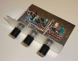
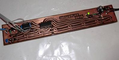
Fig. 6. Effect device Big Muff PI and contactless synthesizer
The contactless synthesizer detects the position of a magnet using eight Hall probes. The analogue signal is processed by a microchip AtTiny 13 and then is sent through a serial link to a PC. However, due to problems with logical analyzer, it was not possible to finish tuning of communication with the PC with available equipment.
Each of sensors provides a different sound. The most faithful sound reproduction is rendered by the piezoelectric pickup, the worse then by the microphone. It was found through experiments that from the time evolution of the recorded signal from sensors it is possible to determine the direction of drawing the bow.
Radio for a castaway
The aim was to construct a functional radio receiver for receiving medium and long waves. Used parts and components were mostly self-made or extracted from electronic waste. To allow all solvers (Víťa Boček, Dan Platil, Tomáš Pivoňka) to participate as intensively as possible in the construction, each of them fabricated their own receiver and they helped each other with creating individual parts. For the construction to be as simple as possible, a receiver with direct amplification without feedback was chosen. A wire antenna with length of about 25 m was stretched in height of 5 to 8 m above the ground. An iron rod hammered into the ground served for grounding. The signal from the antenna is led to a tunable LC circuit and after detection on a germanium point-contact diode to a preamplifier. An amplifier block from a discarded TV with a speaker is used for loud listening. Power supply at 9 V was provided by two 4.5 V lantern batteries. A wooden base board with an aluminum front panel was chosen to provide an easy access to individual parts during the assembly. The whole design and layout of individual parts can be seen in Fig. 7.
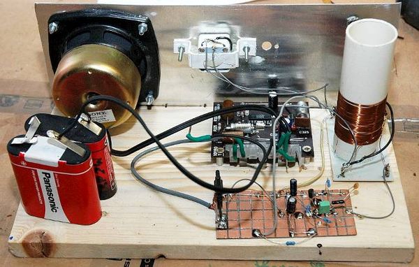
Fig. 7. One of the receivers
Consctructions of individual receivers differed slightly both in component layout and in connections. All receivers were capable of loud reproduction of the programme of the Czech Radio on medium waves and one of them moreover of the stations in the long wave range.
Light communication
The aim of the project was to create a communication light gate with matrix arrangement of 9 light sources that allows transmission that would be visible from the distance of several kilometres.
The solvers (Jakub Šlosárek, Michael Tvrdík, Martina Valešová) first built a prototype about 10×10 cm large with LEDs as light sources. The final construction is a square with a side 2.5 m long with xenon lamps with luminosity of 250 cd as light sources. Both models can be seen in Fig. 8.
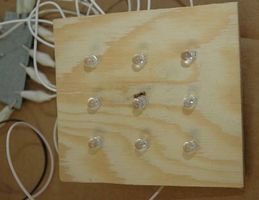
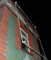
Fig. 8. Preparatory prototype and the final model of the light gate (during transmission)
Our own coding table based on binary coding served to encode individual characters – a six-bit code is assigned to each character (the remaining 3 lights placed in the corners of the gate define the frame of the whole gate).
The solvers built a “keyboard” for a comfortable transmission – each of the nine lights is connected to one of nine copper stripes. The keys have attached small copper plates so that pressing a key connects contacts on the stripes that correspond to a given letter. The final construction of the keyboard can be seen in Fig. 9, a video from the transmission is available on the website of the camp [1].
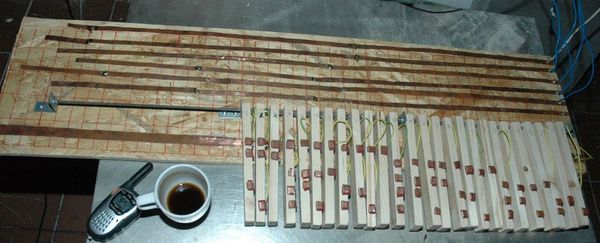
Fig. 9. Keyboard controlling the light gate during transmission
Wave of pendulums
This project was inspired by the video on [4]. The aim of the solvers, Pavel Dušek and Milan Němý, was then to theoretically determine needed lengths of individual pendulums and construct the whole wave. The whole setup can be seen in Fig. 10 – nuts are hung on bifilar hinges made of fishing line and fastened with office binder clips to a wooden construction. Individual nuts are equipped with fluorescence stickers for recording their motion in the dark and under UV illumination.
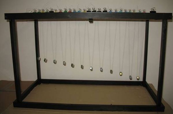
Fig. 10. The apparatus of the project “Wave of pendulums”
The project was eventually extended with creation of a model of the wave and with experiments with coupled pendulums. The solvers then built an apparatus on which they could observe the behaviour of 2-5 coupled pendulums.
The videos from the project are available on the website of the camp [1].
Water integrator
The project of Petra Kaštánková and Veronika Valešová was aimed to build a mechanical device that would serve for illustrative calculation of Riemann’s integral.
The idea was to draw the integrated function on a polycarbonate hollow board (a board with narrow hollow columns) and then to pour certain amount of water into each column and so copy the drawn shape of the function – to “fill up the area below the curve” and to make a calibration table thanks to which the filled volume could be recalculated to the area.
Construction
The bottom edge of the board was after several trials plugged with tinsmith’s putty. Coloured water with detergent for decreasing surface tension was poured into columns with the use of a syringe. A syringe with a tube served for sucking out overfilled columns.
A wooden frame served for fastening the whole board.
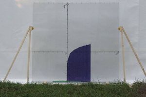
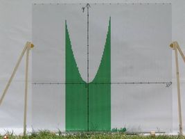
Fig. 11. The final form of the board with filled functions ln x a x2.
Functions
The solvers first calibrated the zero line – they determined the volume of water below the x axis. The volume of one column below the x axis is 107 ml, the whole board with the width of 105 cm has the volume under zero of over 1800 ml. Then the solvers poured successively a linear function, quadratic function, exponential function, natural logarithm, sine function and the Gaussian curve. For most functions the error of the “calculation” did not exceed 10 %.
The following camp
The next camp will be held in Nekoř in Orlické hory in the term July 13th to 27th 2013. In the case you know of any students that might be interested in our camp please let them know of it. You can also contact us on the e-mail address mfsoustredko@kdf.mff.cuni.cz
References
[1] Young physicists’ and mathematicians’ summer camp [online]. Available at: http://kdf.mff.cuni.cz/tabor [cit. 16. 8. 2012].
[2] Žilavý, P., Koudelková, V.: Pár věcí (nejen) z tábora 9. In: Veletrh nápadů učitelů fyziky XI, Conference proceedings, Olomouc, 2006
[3] Mendocino motor a mendocino vozítko. [online]. Available at: http://hawelson.blog.cz/0911/mendocino-motor-a-mendocino-vozitko [26. 8. 2012]
[4] Amazing pendulum wave [online]. Available at: http://www.youtube.com/watch?v=7_AiV12XBbI [23.7.2012]