About paper
Czech originalElectromagnetic Waves in Experiments
In this article, I present how to demonstrate most of the fundamental experiments concerning propagation of electromagnetic waves with the use of a radio receiver, a TV set and a video cassette recorder (VCR), and how to simply and easily show the principles of sound signal transmission, absorption, reflection, polarization and also how to determine the wavelength of electromagnetic waves.
What will we experiment with?
There exists a whole range of professional sets for demonstration of characteristics of electromagnetic waves. We successfully use two commercial sets at our school: a microwave set produced by the former national enterprise Komenium working at 10 GHz with power of a few mW and a modernized set with Lecher wires working at 433 MHz with power up to 10 W that is made by Mr. Hubeňák in Hradec Králové. Besides experiments with these specialized devices, we demonstrate many supplementary experiments with common household items to accurately link the knowledge acquired at school with everyday experience. For these experiments we need a portable radio receiver, an analogue TV set, a VCR and several other things.
Experiments with a radio receiver
A small medium wave transistor radio is suitable for our experiments. The simpler the better. Because advanced receivers are fitted with more effective circuits for equalizing the sensitivity of the receiver to the strength of the signal which is disadvantageous for us. On the contrary, we need the change of the signal strength to be evident in the volume of sound reproduction. The receiver is equipped with an antenna for signal receiving. There are two types of antennas; each uses only one component of the electromagnetic wave (EMW). A wire antenna utilizes the electric component; a ferrite antenna utilizes the magnetic component. The ferrite antenna is a coil with a long core made of soft ferrite that protrudes far from both sides of the coil. It is used to receive medium and long waves because a wire antenna with the optimal quarter-wavelength length would have to be very long for them. The wire antenna is advantageous for short and very short waves because the commonly used VHF range works at wavelengths about 3 m and the length of a monopole antenna for its receiving is about 0.75 m. We will do the following experiments in the middle and long waves.
Localizing a transmitter
The ferrite antenna is always placed horizontally in a receiver because the magnetic component of the EMW is mostly oriented parallel to the ground. The receiver gains the strongest signal if the magnetic field lines pass in the direction of the ferrite rod. On the contrary, the signal is the weakest if the longitudinal axis of the ferrite is perpendicular to the field lines; it is when the axis of the ferrite is directed to the transmitter or when it lies in the same plane with the transmitter antenna. We will find the direction of the weakest receiving by turning the receiver. The transmitter then lies in the direction of the longitudinal axis of the antenna. By directing the antenna to the transmitter from two different positions we can exactly locate the transmitter. Or we can determine our position from the direction of two known transmitters.
The following table can be used to verify the location of Czech transmitters:
| Freq. (kHz) |
Radio station |
Transmitter |
Power (kW) |
Altitude (m) |
Region |
| 270 |
ČRo 1 Radiožurnál |
Uherské Hradiště/ Topolná |
650 |
181 |
Zlínský |
| 639 |
ČRo 2 Praha/ ČRo 6 |
Český Brod/Liblice |
1 500 |
235 |
Středočeský |
| 639 |
ČRo 2 Praha/ ČRo 6 |
Ostrava/Svinov |
30 |
234 |
Moravsko - slezský |
| 954 |
ČRo 2 Praha/ ČRo 6 |
Prostějov /Dobrochov |
200 |
306 |
Olomoucký |
| 954 |
ČRo 2 Praha/ ČRo 6 |
České Budějovice/ Husova kolonie |
30 |
401 |
Jihočeský |
| 954 |
ČRo 2 Praha/ ČRo 6 |
Karlovy Vary |
20 |
433 |
Karlovarský |
| 1 062 |
Country rádio |
Praha/Zbraslav |
20/1 |
335 |
Praha |
| 1 332 |
ČRo 2 Praha/ ČRo 6 |
Moravské Budějovice/ Domamil |
50 |
547 |
Vysočina |
Stations have time restrictions for transmission. More information about transmission and transmitters can be found in [1].
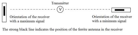
Fig. 1 Orientation of the receiver with a ferrite antenna in respect to the transmitter with minimum and maximum signal
Receiver in a Faraday cage
We put a small radio receiver in an electrically conductive box or we cover it with some wire netting or aluminium foil. The receiving weakens or even ceases. A beverage (milk or juice) tetrapack box is sufficient. An alternative is trying to call a mobile phone packed in aluminium foil. A sufficiently thick layer makes it unavailable.
Sensitivity of the receiver to interference
Turn on a battery charger with switched-mode power supply near a radio receiver. Virtually any switched-mode power supply is a source of interference. The cheaper supply the stronger interference. Quality brand power supplies have such a good interference suppressors that almost no interference can be heard.
Use a TV remote control in a close proximity to the radio receiver. The current impulses that feed the IR diode are also a source of strong interference.
Our own radio broadcasting
We need an RC generator working at sufficiently high frequency of at least 200 kHz, better at about 1 MHz. The BM344 generator is great, the school BK124 generator is sufficient. In addition to it we need a modulator and a source of low-frequency signal such as a tape recorder. The modulator is a device that can be assembled on a piece of wooden board with half-hammered nails serving as soldering nodes. The circuit diagram of the modulator is shown in Fig. 2.
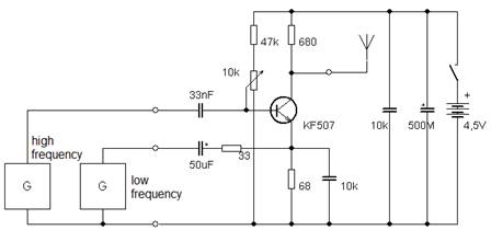
Fig. 2 Circuit diagram of a modulator connected to a high frequency generator and a low-frequency signal source for experimental broadcasting at medium wave
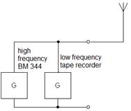
Fig. 3 Circuit diagram of a high frequency generator connected directly to a low-frequency signal source
If we use the vacuum tube generator BM344, we do not even need a modulator and we can connect the generator directly to the speaker output of the tape recorder. See diagram in Fig. 3. We use a 3 – 10 m long wire as an antenna. We set the high-frequency generator on the frequency corresponding to the wave range of the receiver. Receiving of our signal manifests itself as increased noise when we tune the receiver to the frequency of the generator. Then we turn on the tape recorder and set a suitably strong signal with an optimal modulation using the output volume control on the recorder, so that the signal received by the radio is strong and undistorted.
Experiments with TV waves
We need a classic analogue television set and a VCR with high-frequency output. We connect the VCR to the TV with two serially connected coaxial cables so that we can break the signal path in the middle. Then we turn on the video and tune the TV to the appropriate channel. It is good if the television shows the number of the channel so that we can find out the frequency of the transmitted signal. We disconnect the cables and the signal vanishes imediately. Then we allow the signal to propagate in space. We attach small rod antennas to the cable terminals. The signal emerges again.
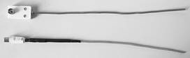
Fig. 4 Rod antennas of the transmitter (upper) and of the receiver (lower)
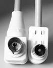
Fig. 5 Close-up of the connectors of the transmitter antenna (left) and the receiver antenna (right)
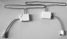
Fig. 6 Transmitting dipole antenna (left) and receiving dipole antenna (right) connected to coaxial cables with sockets through impedance matching elements (in white boxes)
We can get more energy into space and a stronger signal into the receiver if we install a half-wavelength dipole antenna at the end of both the cable from the video and the cable to the TV antenna input. The dipole antenna has strongly directional receiving which allows us to do a row of experiments.
Our own TV broadcasting
We connect the coaxial cable from the TV receiver to a dipole antenna through an impedance matching element. See Fig. 6. The impedance matching element often has a male socket and we can plug it directly to the antenna input of the TV. So we have the receiving. Let us have a look at transmission. The video casette recorder will serve as the transmitter. We connect a dipole antenna to its output to get the signal into space. Here again we need an impedance matching element between the coaxial cable and the dipole antenna. The input to this element must have a female connector. See Fig 5. Having the cable from the video output terminated by the dipole antenna, we can begin to transmit. We need enough space for all experiments because waves reflected from various objects around us can completely alter the outcomes of our experiments.
Directionality of transmission and receiving of dipole antennas
We aim the dipole antennas at each other and move them away to a distance of about two meters. We can see that transmission is going on. Then we aim one of the antennas aside. Transmission gets worse or even ceases completely.
Absorption
We set the antennas to have a good signal transmission. Then we put different materials between them or we stand between them ourselves. The signal can pass through a dielectric, not through a conductor, poorly through a human body.
Reflection
We aim the antennas sideways into space. The transmission is poor or none. We place a reflecting plate in an appropriate position. The transmission gets markedly better.
Polarization of waves
We turn one of the dipole antennas to a vertical position. The transmission gets very poor or even ceases. When both antennas are turned vertically, transmission is renewed.
Interference and wavelength measurement
We put the antennas about 1.5 m from each other so that the quality of transmission is sufficient. We place a reflecting plate just behind the transmitting antenna. The receiving gets much worse. If we move the reflecting plate from the transmitting antenna to the distance of one half of the wavelength, the signal gets again distinctively bad. We measure this distance and calculate the wavelength. If we know at which channel we receive the videosignal, we know its frequency. A table of frequencies can be found in [2]. Knowing the frequency and the wavelength we can easily calculate the speed of EMW propagation.
Note
Any transmission is a subject to the law about running these devices and it is not allowed to broadcast without a permission. Thence I strongly recommend to limit the experiments in time just to show desired phenomenon and not to amplify radiated power by any means.
Reference
[1] http://www.radiokomunikace.cz/
[2] http://www.dx.cz/modules.php?name=News&file=article&sid=188