About paper
Czech originalUsing a loudspeaker and ammeter as a balance
This contribution describes the utilization of a loudspeaker as a compensation power transducer to create a weight balance.
A loudspeaker as an elastic body system
A classical electrodynamic loudspeaker (see Figure 1) consists of a permanent magnet with the magnetic poles separated by a gap with cylindrical shape. At the edges of the gap the permanent magnetic poles provide a concentrated magnetic field of around 1T. The voice coil, which is placed in the gap, is connected to a diaphragm and cap that seals the system from dust. The suspension system which consists of the “spider” and the “surround” keeps the coil in the centre of the gap. The diaphragm usually has a cone-shaped profile and is made from light materials, generally from a special paper. The diaphragm is also connected to a rigid basket or frame. The system of diaphragm with voice coil, which can move elastically, is damped by the air.
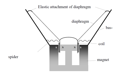
Fig. 1: Dynamic Loudspeaker
Utilization of the loudspeaker as a balance
On the upper edge of the diaphragm of a woofer place a circular board made from solid material, such as a glass fibre laminate. In the vertical position (see Figure 1) the board achieves its equilibrium position in the gravitational field. Now, by putting an object on the board we weight down the board, causing it to move to a new equilibrium position. A force acting in the opposite direction (upwards) is needed to get the board back to its initial position. This force can be provided by the Lorentz force that acts on a coil in a magnetic field. If we connect the coil in the loudspeaker to a regulable source of DC current, the current can be adjusted so that the board moves back to its initial position. In the known gravitational field we can find the relation between the mass of the object and the current needed to obtain the initial equilibrium position of the board. As our type of loudspeaker has a high working stroke, the needed relation is nearly linear. For accurate indication of equilibrium position a simple continuity test circuit with a LED (light emitting diode) is used. Contacts are made from a blade mounted on the table and a tip that is moved by a micrometer screw fixed to the speaker frame (see Figure 2).
At the beginning of the measurement we have to adjust the contacts to the position where the diode just starts lighting. At this time the current inside the coil is zero. By putting an object on the board (in the middle if possible) the diode stops lighting as the contact is broken. Therefore, we have to increase the current until the diode lights up. From calibration we determine a polynomial approximation that can then be used to calculate the object’s mass from the measured current.
In our case we used an ARN 6804 loudspeaker and from a calibration with weights up to 500g we determined the relation: \[ \{m\} = 0.533 \cdot \{I\}. \]
In this relation, when introducing the current in milliamperes we get the mass in grams. We repeated the calibration and proved that the quadratic and absolute terms are negligible and can be ignored; these terms are lower than measurement error and inaccuracies mostly come from adjustments of the equilibrium position. As the edges of the diaphragm are connected by elastic gum we have to consider the influence of temperature on the polynomial approximation.
The accuracy of the measurement is in a short time period 2 percent, in a long time period 5 percent. It is obvious that our loudspeaker cannot compete with a classical balance for accuracy. However, it is a good example of a power transducer where the principles of the compensation method can be demonstrated.
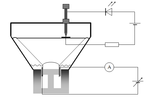
Figure 2.: Schematic of experiment.
Utilization of a computer for automation of the experiment
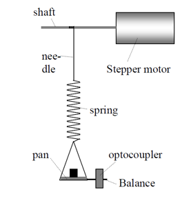
Figure 3. Compensation balance with spring and stepper motor.
Zdeněk Kubů in his diploma thesis considered the idea of automation of this process by using a computer. In this case, the contacts are controlled by a computer serial port and the regulable source is replaced by a D/A transducer. After putting the weighted object in the pan, the current in the voice coil is linearly increased until the contacts touch. From the number of steps used, the program calculates the mass of the object.
Another compensation method that is described in this diploma thesis is based on the utilization of a stepper motor. The stepper motor from a printer was supplied by logic that propagates the electric impulse to individual coils. A thin, long shaft was coaxially connected to the axle of the stepper motor. On this shaft we bound thread to the spring and pan with a balance needle that could block an optocoupler. If we put the object on the pan, the balance needle changed its position (at this time not blocking the optocoupler). This signal was transmitted to a computer that then sent an impulse to the stepper motor. The impulses were counted until the initial position was achieved. From the number of impulses used the mass of the object was determined and displayed on the computer. By changing the spring to one with a different stiffness, the range of measurements could also be changed.
Reference
[1] Kubů Z.: Konstrukce elektromagnetických vah s počítačovou kompenzací. diplomová práce, FPE ZČU Plzeň, 1994.