About paper
Czech originalSome experiments with thermosensitive films
This work focuses on the utilization of reversible thermosensitive films for the detection of temperature changes in experiments with adiabatic compression or gas expansion; for visualization of convection around a suction inlet and imaging of the deflection of a sloping airflow caused by a levitated ball (a demonstration of Newton’s law of action and reaction in continuum mechanics); and for finding nodes and antinodes in a Rubens tube.
Thermosensitive film
Reversible thermosensitive film is made from a special structure based on nematic crystals that changes color in accordance with increasing temperature from black through reddish, yellow-green, green, blue, and back again to black. This change is reversible. The films measure in the range of a few degrees (according to type) and they are fabricated for temperatures from 10°C to 50°C. Due to their low heat conductivity and low heat capacity they rapidly react to changes of temperature.
They very accurately image the distribution of temperature in an area.
In our experiments thermosensitive film from the Omega company was used with a range of 5°C. The technical data for this film can be found in [4].
Notes on thermosensitive films
The reversibility is not 100 %. Places with markedly different temperature histories are noticeable as areas that are a distinct russet shade that does not reset completely to black even if the temperature exceeds the critical value of 100 °C. The color presentation also changes somewhat after contact with some plastics, for example polyethylene foil (probably due to the penetrating plasticizers in the thermosensitive film). A short-term exposure to distilled water does not cause any changes.
Adiabatic processes in a gas
It is not so easy to demonstrate the temperature changes occurring during an adiabatic process in a gas. Gases have a density about three orders of magnitude lower at normal pressure than solid matter and from this the ratio of the heat capacities can be calculated. Whereas heat transfer between the thermometer and the gas is desirable, between the sides of the vessel and the gas it is not; however, in both cases heat is transferred by same mechanism. The only way to eliminate this undesirable effect is by doing the measurements faster than the heat flow from the sides of the vessel influences the thermometer. Therefore you have to heat up or cool down the thermometer to the temperature of the surroundings. From all of this it is clear that the heat capacity of the thermometer must be lower than the heat capacity of the small fragment volume of gas in the vessel and the thermometer has to be as far from the sides of the vessel as possible. The thermosensitive film has a relatively small heat capacity after removing the self-adhesive layer of film.
Practical elements of the experiment
Take a piece of thermosensitive film of size 5x25 mm with temperature range a bit above room temperature (e.g. 25-30 °C). Peel off the backing and stick the film on a balsa prism (or use matchsticks) of size 3x3x100-120mm. Attach the other end of the matchstick to the cap of a PET bottle using a glue gun. All of the redundant layers should be removed from the film in order to have the smallest possible heat capacity. Then, screw the cap onto a large, long PET bottle (see Figure 1).
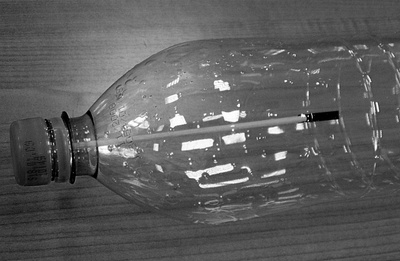
Figure 1
If the temperature in the room is lower than the lower limit of the temperature range of the film, heat up the air in the bottle (by using your hands) until the film starts to change its color from black to russet. After this squeeze the bottle tightly. The film reacts to the adiabatic heating by changing its color with a delay of about 1-2s. It is important to keep the bottle in a vertical orientation and press it as high above the film level as possible in order to reduce the heating from warm hands. After releasing the bottle wait until the film has returned to its initial color.
For a small relative change of temperature and pressure during adiabatic compression we obtain the relation: \[\frac{\Delta T}{T} \approx \left(1-\frac{1}{\kappa}\right)\cdot \frac{\Delta p}{p} \qquad \left(1-\frac{1}{\kappa}\right) = \frac{2}{7} .\]
A temperature change of about 5 °C from room temperature during adiabatic compression/expansion corresponds to a pressure change of about 6 000 Pa from atmospheric pressure.
Characterization of the convection of air during suction
The explanation of the hydrodynamic paradox of tubes bucking against the flow of sucked air [2] is based on the claim that the air is sucked from all directions. We will verify this claim. Make an incision in the plane of the axis of a transparent tube with diameter around 10 cm (e.g. from a hand whisk) and put there sheets of thermosensitive film and a regulable source of suction (at the level of a ventilator). Then by using the tip of a hot soldering iron we can create a hot-air mark that as it is carried away along the film creates a trace imaging the appropriate flow (see Figure 2). To prevent damage to the thermosensitive film from solder, it is good to isolate them by using sheets of paper.
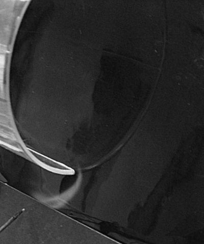
Figure 2
The trajectory of “hot-air” particles is well seen in Figure 2 and it is obvious that the inlet sucks in from all directions. The visible trace is kept for a few tenths of a second.
The imaging of flow around the suction inlet can be done in another way by considering the latent heat of vaporization (for water around 2500 J·g-1) – see Figure 3. If we cover the thermosensitive film with drops of distilled water, the place where the water evaporates will be colder. The film can then image the distribution of evaporating water. The temperature range of the film used has to be much lower than the temperature of the surroundings. It is necessary to try it out ahead of time. In high humidity this effect does not work. If we adjust the suction to lower values we find out that with the film behind some obstacle (for instance a thin matchstick) it indicates a lower temperature. This is due to the turbulence that is carried away by the suctioned air. Turbulence is responsible for high local evaporation and therefore higher cooling.
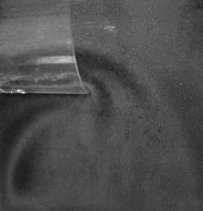
Figure 3
Comment: This method provides only very approximate imaging of flow. The character of the flow is affected by the friction between the air and the thermosensitive film.
Ball levitation
Another experiment is ball levitation in an inclined flow [3]. From Newton’s laws we know that the ball is levitated if the net force acting on the ball is zero. The vertical force acting against the force of gravity originates from the pressure field that is created around the ball. This pressure field also acts on the air flow. As the air flow is inclined, the pressure field will incline it more (see Figure 4). This observed effect is a demonstration of Newton’s third law.
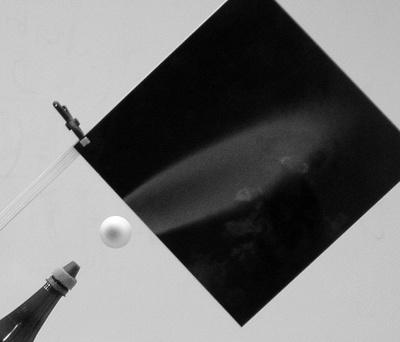
Figure 4
The flow can be imaged by using a smoke source and suitable lighting. Another possibility is using thermosensitive film with a suitable temperature range (for temperature 25°C, film with a 25-30°C range works well), that we vertically put into the axis of air flow behind the place where the levitated ball would be. The appropriate temperature of the air can be controlled with a hair dryer. We can image the direction of the air with and without the ball. An advantage of this method, apart from its relatively simplicity, is the fact that both images can be seen simultaneously (see Figure 5.
Comment: The air generator is not suitable for suction of the hot air.
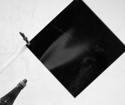
Figure 5
Imaging of nodes and antinodes in a Rubens tube
A Ruben’s tube (similar to a Kundt’s tube) is an acoustically resonant tube that is made from a thin-walled metal pipe. The tube is regularly perforated along the top along the tube axis. Apart from a small speaker for inducing acoustic signals it also contains a small tube attached to a supply of a flammable gas [4]. (simple model [6]).
The gas leaks from the perforations under a pressure that is sum of the continual supply pressure and the local acoustic pressure. The mean value of gas flow determines the positions of the nodes and antinodes [4], [5]. There are a few ways to image these nodes and antinodes. If we supply flammable gas into the tube and light it above the perforations, imaging can be done by examining the height of the flames. This is very effective, but the heating of the tube causes its detuning. A second possibility is using thermosensitive film that is placed parallel with respect to the leaking air. Then fill the tube with hot air. However, there is same problem with tuning. In both cases the diameter of the perforations has to be very large, as with a greater amount of leaking air, the detuning is less.
If we cover some thermosensitive film with drops of distilled water and put it parallel with respect to the perforations, we can better distinguish the differences in air flow from the perforations, even when the same temperature exists outside and inside of the tube. The air flow and therefore water evaporation increases if the acoustic pressure is higher in the perforation. Higher evaporation yields a decrease of temperature. Considering the specific latent heat of vaporization (2500 J·g-1) and the fact that the cooling effect is cumulative, the diameter of the perforation could be made lower. The tube have lower inhibition. This effect does not work if the humidity inside of the tube is high.
Figure 6 shows the positions of antinodes of acoustic pressure as imaged on the film.
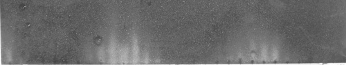
Figure 6
References:
[1] http://www.omega.com/ppt/pptsc.asp?ref=LCS_LABELS&Nav=temf01
[2] Konečný P.: Pokus o kvantitativní interpretaci jednoho hydrodynamického paradoxonu. In: Sborník konference Veletrh nápadů učitelů fyziky 7. ED.: Svoboda E., Dvořák L. Prometheus Praha, 2002
[3] Konečný P.: Několik experimentů z hydrodynamiky. In: Sborník konference Veletrh nápadů učitelů fyziky 8. České Budějovice, 2003
[4] Geoge F. Spagna, Jr.: Rubens flame tube demonstration: closer look at the flame. In: Am. J. Phys.51, 848 (1983)
[5] G. Ficken and F.C. Stephenson, Phys. Tlach. 17, 306 (1979).
[6] Konečný P.:Z jídelního lístku fyzikální kavárny při ÚFE PŘF MU aneb Kundtova a Rubensova trubice In: Sborník konference Veletrh nápadů učitelů fyziky 12. ED.: Svoboda E., Dvořák L. Prométheus Praha, 2007