About paper
Czech originalExperiments with ultraviolet and infrared light
Introduction
Ultraviolet (UV) and infrared (IR) light are the closest neighbours of visible light in the electromagnetic spectrum. Both types of radiation are out of the range of human sensual perception, which is an inconvenience for the teacher working with younger students.
It is possible to make UV and IR light ‘visible’ and give the students evidence of their existence. UV light can be brought into the visible part of the spectrum by using luminescence, and IR light can be visualized with the use of a convenient camera equipped with IR night vision (1, 2). When implementing the experiments some technical problems can arise, especially finding an intensive source of UV light, obtaining UV optical elements and appropriate luminescent materials, and separating the IR light from the visible part of the spectrum. Some experiments allowing the visualization of both the UV and IR parts of spectra using relatively common devices are described in this paper.
Luminescence
Luminescence, or to be more precise, photoluminescence is the emission of light caused by the absorption of electromagnetic radiation. An incident photon transfers its energy to an electron which is excited from a lower energetic level E1 to a higher one E2. If a spontaneous return back to the first level occurs, a photon of the same energy as the incident photon is emitted (fig. 1, left side). If the electron loses part of its energy while in the excited state E3, for example in an interaction with the thermal oscillations of the atoms, it can move to a lower energy level E2 and then cross a lower energy gap in the jump back to E1. Thus the emitted photon has lower energy than was the energy of the incident photon. This is how the invisible UV radiation can be transformed into visible light.
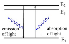
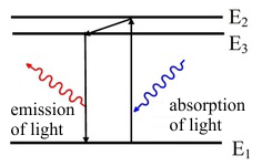
Fig.1: Photoluminescence of light. The emitted light can have the same wavelength as the incident light (left) or a longer wavelength (right).
Photo-luminescent materials are available on the market, but it is possible to use just a plain white sheet of paper. The paper emits blue light by the photoluminescence mechanism, so only radiation at energies that are higher than or equal to that of the blue light can induce the luminescence (fig. 2).
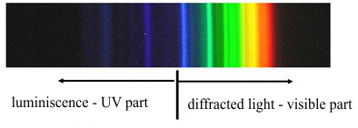
Fig. 2: Spectrum emitted by a white sheet of paper on which a Mercury discharge lamp is shining.
The fact that the luminescence can be excited only by radiation of shorter wavelength is the consequence of a fundamental law of nature: the energy of electromagnetic radiation is emitted in quanta, and the explanation could be the same as that of the photoelectric effect. This fact may also be demonstrated more obviously, if we use luminescent foils with different colours of emitted light. The result of the experiment is illustrated in fig. 3. The spectrum of the mercury gas-discharge lamp shining on the red foil is all red, whereas that on the green foil is green, beginning at the green spectral line and continuing down to the shorter wavelengths.
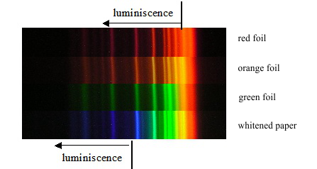
Fig. 3: Spectra of the mercury-gas-discharge lamp on foils of different colours.
Physical paradox-changing the colour of the light by reflection
Luminescence can be demonstrated in a simple experiment which invokes the illusion of physical paradox. If we light a red luminescent foil with a green laser, the spot of incident light will shine in red to all directions; whereas the reflected beam is green. If we conceal the fact that the incident light is green, we will be under the illusion that the reflection of the light changes its colour (fig. 4). It is appropriate to complete this experiment by showing the case in which a red laser is shining on a green foil. The red light can not excite the green luminescence; thus the trace (spot where the laser hits the foil) of the laser still stays red.
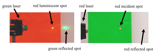
Fig. 4: The reflection of a green laser on a red foil and of a red laser on a žgreen foil
Sources of UV light
An ordinary bulb, whose spectra is given by Planck’s law, is a very weak source of UV radiation and because the maximum temperature of its filament is limited by the melting point of material used (tungsten), it is not technically possible to improve the situation. It is necessary to use a gas discharge lamp for generating the UV light, but the main disadvantage of such a solution is the price which is higher than that of a plain bulb. A mercury gas discharge bulb can serve as an intensive source of UV radiation, so the possibility of using an artificial sunlight lamp, which was available on the market of household electronics in the past, arises. The main disadvantage of artificial sunlight is that together with the switching on of the mercury lamp, the IR tube, which is already switched on, becomes hot and it complicates the manipulation of the source and also makes it difficult to do some experiments (such as the construction of a spectrometer, in which the aperture has to be very close to the source of light). IR tubes are essential for the proper functioning of the artificial sun devices, because they serve as the series resistor. If we place the lamp into an isolated chamber and replace the IR tubes with glow discharge bulbs connected in series, we gain an intensive source of UV light which can be used for the demonstration experiments instead of a separate mercury gas discharge lamp. All experiments in this protocol were done with the use of the artificial sun’s gas discharge lamp.
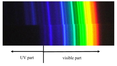
Fig 5: The spectrum of a Xe gas discharge lamp
UV optics
Optical elements are usually made of glass, but the glass absorbs the most of the UV radiation. Visible light mostly passes through; thus glass optics can be used in that case. Professional UV spectrometers use optical elements made of other materials such as quartz. If you have quartz optics, the absorption of UV light in glass can be easily demonstrated (fig. 6). Quartz optics are much more expensive than glass ones. To construct a spectrometer, two optical elements are required – a lens and a dispersion element (prism or grating).
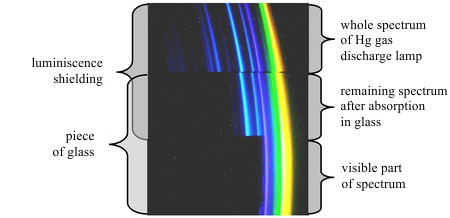
Fig. 6: Spectrum of the Hg gas discharge lamp
UV Lenses
The absorption of UV light, negligible in water, allows us to construct a water lens by pouring water inside a glass of proper shape that is transparent to UV light. The easiest option is to pour water into a low-density-polyethylene (LDPE) bag which can be easily formed into the shape of a cylinder, as is illustrated in fig 7. This cylindrical lens is sufficient for the construction of a spectrometer with a linear aperture and it is possible to observe spectra of satisfactory quality (fig. 7).
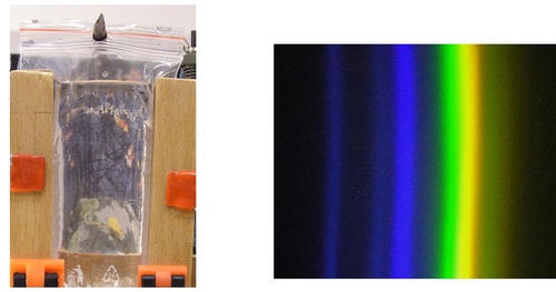
Fig .7: Water cylindrical lens (left) and the spectra of the mercury gas discharge lamp obtained using this lens (right)
UV dispersion elements
It is easy to create a cylinder from LDPE or some other element which serves both as a cylindrical lens and as a prism. We are facing a serious problem in that case. The dispersion of light in water is very little (depending on the index of refraction and the wavelength); thus the water cylinder does not decompose the light into spectra with sufficient resolution. This paper’s authors haven’t yet succeeded in finding a readily available liquid with dispersion fulfilling the conditions necessary for the construction of a dispersion element for UV optics.
A quartz prism can be substituted by a crystal which can be bought easily. Fantastic results can also be obtained with a reflecting grating, but just as in the case of the quartz prism, this element is not readily available on the market.
Even you do not have the UV optics, a sufficient visualisation of UV light can be obtained with glass optics, as is obvious in fig. 6.
Sources and the detection of IR radiation
The two basic principles used for the detection of IR radiation are
1) Thermal effects (bolometers)
2) Quantum detectors (photodiodes)
Both options can act as educational experiments, even allowing IR visualisations of the object. Thermal effects are detectable with thermo-sensitive foils, and an IR camera with night vision can be used as a quantum detector. A bulb is a suitable source of IR light. The following nice demonstrations of the existence of IR radiation can be obtained only if it is possible to separate it from the visible spectra of light. These experiments, fortunately, do not have any real technical problems.
The separation of IR radiation from visible light
There are three ways to separate IR radiation from visible light:
1) Use a source which emits only IR radiation, not visible light. The easiest way is to use an IR diode such as that in a TV remote controller, but it is very impressive to visualise the IR radiation arising from hot objects such as a hot electrical cooker. Either the thermo-sensitive foil or the night vision camera can be used for the detection.
2) Separate the IR part of the light by using a prism spectrometer with glass optics. The camera can be used for detection.
3) Use a filter which absorbs the visible light and transmits the IR part. A silicon disk, which may not be readily available, can be used as the filter. There are also additional options that use common materials.
Different materials that may be used for IR filters
The spectral dependence of transparency of filters made of selected materials are depicted in fig. 8, such as exposed and developed colour and black-white films, black polyethylene foil , black permanent marker on glass and a professional IR filter (Edmund Scientific) for comparison, respectively. All these mentioned films are partially transparent in the visible part of the spectrum, a fact that is obvious even in looking out of the window. None of these filters reaches the quality of the silica disk.
The black-white film negative is the most absorbing filter so it is useless for our purposes. Better results can be obtained with a black polyethylene foil for which a huge advantage is the good accessibility even in large quantities. The main disadvantage of polyethylene foil is its non-homogeneity and dull surface that deteriorate the quality of the image. Good results can be obtained with colour film negatives which are, however, not necessarily readily available. The best experiences were gained by darkening glass with a layer of black marker, which gave spectral transparency very close to that of professional IR film.
The best quality filter can be prepared by putting a black marker’s filling on the glass, spreading it by tilting the glass slightly side to side and letting the liquid evaporate. Obviously, it is not sufficient to have only a single layer; thus it is better to spread the paint onto both sides of the glass. If it is necessary, more filters placed together can be used and the situation in which the system is non-transparent to human eyes can be reached.
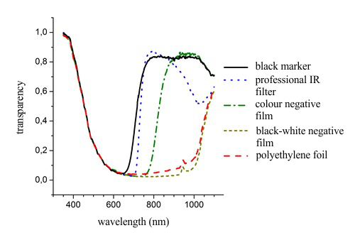
Fig. 8: Spectrum of transparency for selected filters
An example of an experiment with the marker filter is illustrated in fig. 9. Both photos have been taken by the same camera. The non-filtered image is on the left side, the one obtained with the filter is on the right side. The photos illustrate two sources of light. The candle is an example of a source with a high fraction of the IR light, whereas the source containing white LED diodes emits a very low fraction of IR light. Looking directly at the sources, the LED diode’s outgoing light is brighter than that of the candle. The pictures captured with the digital camera, which has high sensitivity even in the regime without night vision, shows that the candle brightness dominates in the IR part of the spectrum. It is interesting to notice that the image taken with the filter is blue-violet, which is a consequence of higher transparency for the shorter wavelengths (fig. 8).
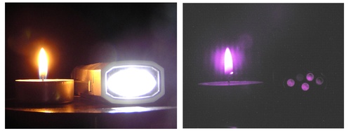
Fig. 9: Experiment with an IR filter made of black marker on glass.
Remarks
The indispensable parts of this paper are the colour versions of all photos presented here. Because the printed version is in black and white, we recommend readers to read the electronic version of the documents. Please contact the authors if you would like the electronic version (zboch@physics.muni.cz.)
Most of these experiments are observable by the unaided eye. The dynamic range of the human eye is different in comparison with that of the camera; thus the photos presented here were slightly modified to bring the results closer to typical human visual perceptions.
References
[1] Bochníček, Z., Strumienský J.: Pokusy s termocitlivými fóliemi. Veletrh nápadů
učitelů fyziky 12, sborník z konference. Praha 2007. s. 16-2.
[2] Bochníček, Z. An amateur video camera as a detector of infrared radiation.
Physics Education, vol. 43, no. l, s. 51-56.