About paper
Czech originalTwo experiments with a CD diffraction grating
Two simple experiments with a CD, which works quite well as a reflecting optical diffraction grating, are briefly described in this article. The experiments allow estimation of the wavelengths of diffracted rays of light.
Experiment no.1
The experimental setup is illustrated in fig. 1. As a source of light, a convenient electrical lamp labelled as L is used. The beam passes through a slit S, which can be made of things that are usually found at home like two big books, two tea packs, two CD cases, etc. The beam of light strikes at a point on the CD disk. The intensity of diffracted rays that are shining on the paper P placed on the table can be increased by moving the lamp. It is very simple to fix the CD in the vertical position – the CD disk is mounted by its middle hole on the pen C, overlapping the edge of the table.
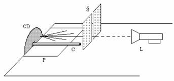
Fig. 1
Because the source of light provides whole spectrum of visible light, diffracted rays also show the entire spectrum. The only exception is the diffracted beam belonging to the zero maximum. Measuring the angle of some diffracted rays when the incident light is perpendicular to the CD plane, the wavelength can be calculated using the equation \[\tag{1} \lambda = \frac{\mathrm{O_1O_2}}{i} \sin \alpha, \]
where i is the order of the maximum, O1O2 = 1.6 mm is the grating spacing which can be calculated from the density of tracks in a CD disk (if there are 625 tracks in a millimetre).
If we determine the angle a1 belonging to the first maximum i = 1, the wavelength is then expressed as \[\tag{2} \lambda = \mathrm{O_1O_2} \sin \alpha .\]
Experiment no.2
In this experiment, the CD disk is placed on the table. A paper shield with a small circular aperture O in the middle is placed above the disk. The edges of the paper are fixed by two books, K. The incident laser beam passes through the aperture and one observes the diffraction pattern belonging to the particular maximum (fig.3). Diffracted rays lie in a plane perpendicular to the direction of traces at an appropriate point of the disk. The place which is the most suitable for the beam incidence is the area near the outer edge of the disc.
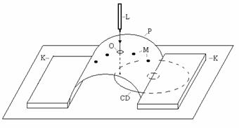
Fig. 2
Looking at the set-up illustrated in fig. 3, we do not see the light point belonging to the zero maximum, because appropriate ray escapes through the aperture O. If the incident beam is tilted slightly, the trace of light belonging to the zero maximum appears.
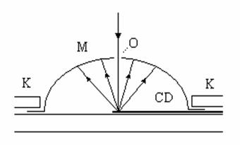
Fig. 3
References:
[1] I. Baník, R. Baník: Meranie vlnovej dĺžky svetla pomocou CD platne, MFI 5, 1996, s. 26-29
The paper was written with the support of ESF and a grant KEGA.