About paper
Czech originalHeat experiments
The following text describes several suggestions that can be used in physics lessons that concern the topics of heat, heat transfer and heat machines. The main issues discussed here are: how to make an alcohol burner, a calorimeter or a heat engine/heat pump; how to utilize thermal paper; how to demonstrate the functioning of a heat pipe; and some additional topics.
Burner – A basic heat source
For students to get some experiences with heat and temperature, it is necessary to have a sufficient number of heat sources. A disadvantage of a candle is the smoke that it produces; a gas burner is expensive. An alcohol burner is sufficient for most experiments. It can be made in the following way. Let us use a baby food jar. The lid is made of a tin-coated metal sheet. We now prepare a wick-tube that can be attached to it. It is easy to make with a bit of soldering. A copper pipe from an old refrigerator or a brass ballpen refill works well (Fig. 1). Drill or puncture a hole with the same diameter as the tube into the lid and solder the tube to the hole. If soldering is not an option, it is simplest to use a tube with a screw thread, for example, from a chandelier rod (Fig. 2). Fasten the tube to the lid with two nuts. Thread a cotton wick through the tube, pour alcohol in the jar and the burner is ready.
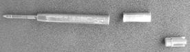
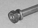
Fig. 1: Parts of a refill. Fig. 2: End of a chandelier rod.
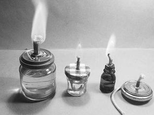
Fig. 3: Some types of alcohol burners
Heat conduction and thermal paper
Thermal paper is useful to probe how much some material is heated. It is used today in cheaper printers and fax machines. It can be bought in rolls of different widths. We cut suitable sheets (size A4) of the paper and straighten them between boards in advance. The paper turns black when heated. Thus, we can easily display regions of some object with different temperatures or we can display the conduction of heat along the material.
For a nice heat conduction experiment, prepare two similar tubes of length about 10 cm with the same diameter and appearance, made of two materials with different thermal conductivities. A good pair of materials is copper and iron. Chromium-coated copper tube with a diameter of 10 mm is used by plumbers to connect taps, tankless heaters and so on. A standard chandelier tube used for hanging ceiling lamps is made of iron and has the same diameter and a chromium-coated finish.
Have two students hold the two tubes by hand at one end and heat the other end of the tube above the flame. The copper tube soon gets so hot that it cannot be held by hand. Let both students lay their tubes on the thermal paper at that moment. We press the tubes with a board and roll them along the paper. The copper tube leaves a faint trace as wide as the tube’s length. Thanks to its high thermal conductivity, the copper pipe was heated homogenously and has the same, quite low temperature across its length. The trace left by the iron pipe is quite different. The width of the trace is about one third of the tube’s length and it is much darker at one end of the tube. The end that was put over the flame was heated to a quite high temperature while the other end remained cold. The temperatures at different points of the tube differ very much. The thermal conductivity of copper is about 8 times higher than that of iron.
A simple calorimeter
A physics teacher often faces the problem of obtaining a larger number of cheap and usable calorimeters. Students can fabricate the following simple calorimeter themselves. The materials needed are a beaker, a strip of thin plastic foam, a 10 cm high bottom section of a PET bottle and a polystyrene board. Wrap the beaker in the plastic foam and push it into the bottom of the PET bottle. Cut a lid with a hole (for the thermometer) from the polystyrene board with a knife. In case of a shortage of glass beakers we can manage with just PET bottles. In this case we cut two bottoms: the first bottom is from a 1.5 liter bottle, 8‑10 cm high; the second one is from a 2 liter bottle, 3‑4 cm higher than the first one. We wrap the first bottom with plastic foam and push it inside the larger one. This type of beaker does not have a lip for pouring.
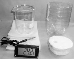
Fig. 4: Parts for manufacturing of a calorimeter. A digital thermometer is not necessary but very useful. It is mechanically durable and sufficiently sensitive.
Heat pipe
How can one remove and transfer heat without performing work when the thermal conductivity of metals is not sufficient? R. S. Gaugler suggested a solution in the year 1942 but the development of his idea, the heat pipe, did not occur until many years later. It is increasingly popular in computers today to remove heat from the CPU. It consists of a thin-walled copper pipe. Its inner walls are covered with a microporous material saturated with a volatile fluid. The inside of the pipe is filled only with the saturated vapor of the volatile fluid. The fluid evaporates at the hotter area of the pipe and flows to the coolest point where it condenses. Capillary forces quickly return the condensate to the hotter area. Evaporation consumes the latent heat that is released during condensation. This process maintains the thermal gradient across the pipe at a minimum. The pipe outwardly seems to have a huge thermal conductivity.
The following table shows data for various fluids used in heat pipes
| Fluid |
Melting point (°C) |
Boiling temperature at standard pressure (°C) |
Range of applicability (°C) |
| Helium |
−271 |
−261 |
−271 to −269 |
To demonstrate the heat pipe in action, connect two calorimeters to it. The calorimeters are made of 0.33 l beer cans, each wrapped in plastic foam and pushed into a bottom of a 1.5 l PET bottle. The pipe is placed with electrical bushings into the walls of the cans. The time evolution of temperature in the calorimeters shows that a 12 cm long pipe with a diameter of 6 mm transfers 0.8 W thermally at a temperature gradient of 1 °C. A copper rod of the same dimensions would transfer only 0.09 W/°C and would be four times heavier.
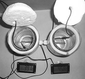
Fig. 5: Calorimeters made of beer cans connected with a heat pipe.
Model of a heat pipe
We can easily manufacture a model of a heat pipe. Instead of a microporous layer, the fluid is brought back to the place of evaporation only by gravitational force. We use a glass pipe so that we can see inside. The disadvantage of glass is its poor thermal conductivity in comparison with copper. The heat that is transported has to overcome high thermal resistance at the input and also at the output from the pipe. The performance of the pipe is thence very different from the performance of a copper heat pipe.
To manufacture the pipe, seal up one end of a glass tube of sufficient length (at least 60 cm). Pour some ethanol (about 10 cm of height) inside. Add some boiling chips for a smoother boil. Put a piece of rubber hose (about 10 cm long) on the other end of the pipe. Attach a screw clamp at the end of the hose and clamp it so that there remains only a slim aperture. Begin to heat the pipe carefully over a burner or even better, in boiling water. Let the ethanol violently boil until the whole inside of the pipe is heated to the boiling temperature and gaseous ethanol is seeping out of the hose. Move the pipe away from the heat source and immediately close the clamp tight. Ethanol continues to boil but the squeezed part of the hose between the clamp and the pipe gives us evidence that the pressure inside the pipe is lower than outside. The heat pipe is complete.
Put one end of the pipe in a vessel with hot water. A violent boil takes place in the pipe. The fluid is evaporating, and then it condenses at the pipe’s other end. After a moment we can barely hold it in our hand. The heat is transported from the hot water to the other end of the pipe where it gets to the surrounding air and the water in the vessel quickly becomes cool.
Heat-work machines
There are two types of heat-work machines. The first is the heat engine which converts a part of the heat that is transferred from a hot source to a cold sink into work. The other is the heat pump which moves heat from a cold source to a hot sink using work. We can easily demonstrate both these machines with a Peltier cell. Its scheme is depicted on Figure 7. Many different types are manufactured. The prices of the cheapest ones start at USD 10. The Peltier module on Figure 6 consists of 72 cells connected in a serial circuit. They are connected with copper bridges and put between two ceramic surface plates. The dimensions are 30 x 30 x 4 mm.
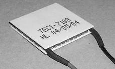
Fig. 6 Peltier module.
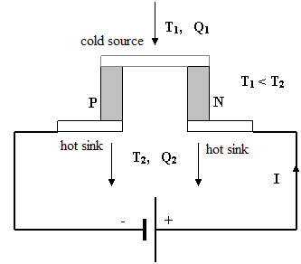
Fig. 7 Scheme of the Peltier cell working as a heat pump. The cold source is cooled by the electric current to temperature T1 accepting heat Q1. This heat is transported by current to the hot sink which is heated to temperature T2 releasing heat Q2 which is the sum of Q1 and the heat generated by the current. The main materials for thermo-electric semiconductors are bismuth tellurides: BiTeSe (N type) and BiSbTe (P type). The contacts between them are made of copper plates.
If we connect the module to a current source, one ceramic plate is markedly cooled and the other heated. It works as a heat pump and we can use it to cool something. Some battery cool boxes and active coolers in electronics work with this principle. If we conversely heat one plate of the module and cool the other, the module becomes a voltage source. An appropriate device such as a little electromotor will work if connected to the module. The direction of rotation changes with a change of the current direction.
If we heat the cold sink and cool the hot source, the polarity of the module and the sense of rotation changes. We can show that the electrical performance grows if the difference of temperatures between the plates becomes larger. It is not sufficient only to heat the module. We must also let the heat move from the hotter part to the colder part of the system. Be careful to observe the current and temperature limitations given by the producer of the module because it is a semiconductor device.
Heat weighing
Finally, we will show how easy it is to prove the validity of the Einstein’s equation E = mc2. J
Prepare an aluminum rod (or tube) with a hole in the middle slightly above the center of mass (see Fig. 8). Hang it on a stand so that it can rotate. We used a pin with a glass head dug in a cork as the axis. The rod is hanging in the horizontal position. We heat the rod at one end and comment: “The heat provided to the rod by the flame increases the energy of the particles and thus their mass is also increasing. The arm of the rod that we heat becomes heavier than the cold arm.” Than we heat the other arm of the rod and see that it goes down after a while. The correct explanation is not so poetic, of course. The rod elongates when heated and its centre of mass moves sideways. The rod then finds a new equilibrium with the centre of mass below the pivot point.
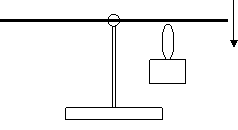
Fig. 8 Heat weighing set.
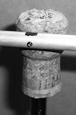
Fig. 9 The detail of the axis of the rod.
Recommendation
You will find other interesting information and suggestions for work in a high school laboratory at: http://fyzika.gymnachod.cz
References
[1] http://lukepage.wz.cz/hardware/cooling.htm