About paper
Czech originalMeasurement of the magnetic field
Measuring of the B-field in a high school laboratory is not very common – there are no affordable measuring devices. The USD prices of brand new precise devices are expressed in three digit numbers, and classical flux meters and Tesla meters are usually past service.
A Tesla meter with Hall probe utilizes a phenomenon discovered and described in 1879 by the American physicist Edwin Herbert Hall (1855-1938, Harvard University Professor). Current flowing through a flat sample is affected by a perpendicular magnetic field in such a way that a voltage occurs perpendicular both to the current and to the magnetic field on the sample. The source of this Hall voltage is the force that affects charges in motion.
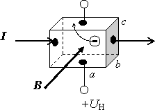
It is not difficult to show the following formula in high school physics lessons: \[ U_H = Bc \frac{I}{bcne} = \frac{I}{bne} B. \]
While Hall was working with thin metal foils (the b dimension must be as small as possible) and a high concentration of electrons, today’s Hall probes contain a slice of semiconductor with a relatively low concentration of charge carriers (for example a piece of doped GaAs). The area of the slice is less than a square millimeter and the thickness b is around a tenth of a millimeter. The Hall voltage is about 100 mV at magnetic field B = 0.1 T and current I = 5 mA.
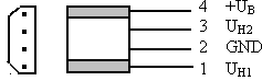
The Hall probe can be easily obtained from a 5¼-inch floppy disk drive from an old computer – it can be found in every school. Beneath the rotor there is located a set of stator coils and on the printed contact board we usually find 3 Hall probes – little cuboids with two beveled edges made of black plastic with four terminals:
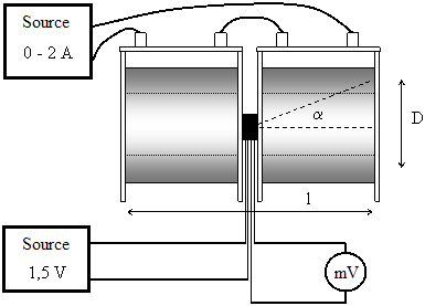
If there is not a factory made Tesla meter in the school, we can use an alternative device to calibrate the probes. It consists of two coils (for example 1200-turns coils from a demonstration transformer), a DC source, an ammeter, and a millivoltmeter. Between two coils connected in series there is created a magnetic field \[B = \frac{\mu_0 NI}{l} \cos \alpha.\]
We must settle for some uncertainty due to the non-ideal shape of the multilayer winding of the coils. The l is the measured length of the winding of these two coils and cos α is related to the mean diameter of the coils’ winding D (see the figure below). With our values we get \[ B = 18.3 \cdot 10^{-3} \cdot I (\mathrm{T}).\]
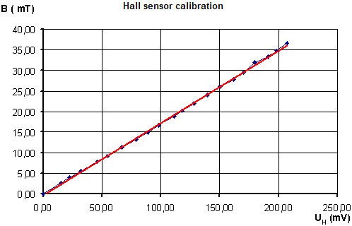
The calibration curve can be quite sufficiently approximated with a linear function and thus extrapolated within the range from 0 to 100 mT.
Measuring with the Hall probe
An ideal voltage source for the probe is a 1.5 V alkaline battery which will retain a stable voltage during the whole measurement (the load is about 5 mA). We measure the Hall voltage with a digital multimeter in the range of 200 or 400 mV.
B-field at the axis of a cylindrical permanent magnet
We gradually move the probe away from the end of the magnet and pay attention to the geometry of the configuration. The dependence of the B-field on the proximity distance x is shown in the following graph.
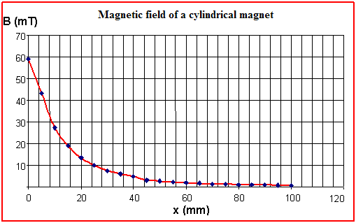
A very fast decrease of the B-field is evident – the field of a 124 mm long rod magnet is negligible already at a distance of 100 mm.
B-field at the axis of a ferrite ring magnet
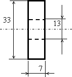
The measurement is organized in the same manner as before. The dimensions of the ferrite ring magnet (in mm) are given in the following figure:
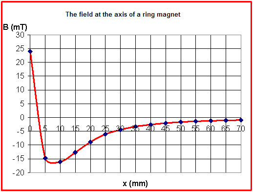
The graph below shows an interesting fact: the magnetic field reverses its orientation in the proximity of the ring magnet and at the axis there is a point with zero field.
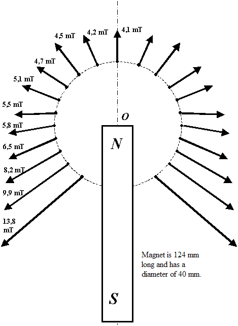
The vector field around the head of a rod magnet
We rotate the Hall probe at the point of measurement until the voltmeter indicates a maximum of the voltage. The vector of the B-field is perpendicular to the probe with good accuracy and the value of the field is given by the calibration function obtained from the first graph as \[ B (\mathrm{mT}) = 0.175\cdot U_{H} (\mathrm{mV}).\]
If we choose a set of points around the end of a rod magnet, we can draw the B-vector field at a suitable scale. The following figure shows the results of the measurement of a 124 mm long permanent magnet with a diameter D = 20 mm. The points are located at a circle with a radius of 40 mm.
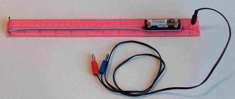
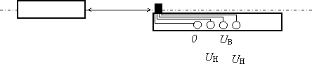
The probe is in the upper left corner of the figure. The battery is a part of the set and the contacts are ready to be connected to a millivoltmeter.
The result is an interesting picture of the B-field vectors:
The Hall probes are currently being replaced by sensors with asymmetric magnetoresistance (AMR) or giant magnetoresistance (GMR). Search the Internet for further information: