About paper
Czech originalSimple Experiments
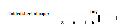
Weighing rings with a piece of paper
Tools: sheet of typing paper (80 g/m2), tack, ring, ruler
Setup:
Description:
First I explain to my students, what the A format of paper actually means. It is a rectangle, the sides a andb of which are in such proportions that when folded crosswise, we get a rectangle with half the surface similar to the original. Therefore a : b = b : a/2. A derivation gives us the formula a = √2 ·b. The biggest rectangle labelled A0 has a surface of 1 m2, A1 has half that surface, therefore 0.5 m2. Through further division we get to the result that A4 format has the surface of 1/16 m2. The paper used in printers has a grammage of 80 g/m2. The A4 paper weighs exactly 5 grams. It is good to prove this with accurate scales and demonstrate to the pupils.
We fold the paper crosswise to mark the centre point. Then we fold it lengthwise several times to get a thin folded strip of paper, on which a ring can be placed. The length of the strip is the same as the height of the paper, i.e. approximately 30 cm. We put a tack through the marked centre S. Then we widen the hole slightly so that the paper is free to rotate. Everyone can therefore prove that the centre is also the centre of gravity. According to the expected weight of the weighed item we choose a suitable distance from the centre, where we make another hole with the tack. As a starting point I recommend a = 4 cm. This point is marked T. We slip the ring on and balance it with the tack placed in point T. We mark the position of the ring. Then we determine the length b of the ring from the rotational axis T. If the weight of the paper strip is mp, then the weight of the ring m can be determined with the formula m = a/b mp. If the ring is very light, it is advisable to divide the paper lengthwise into two or even four parts. The weight mpwill then be 2.5 g or 1.25 g, respectively.
Notes
1. When looking for the balance point we can make our work easier, if the holes are a little higher than the middle of the strip. We can hold the tack in our hand, but it is easier to stick it in an object at hand. An eraser, a pencil, a notice board etc. This experiment can be designated practical work. Students can determine the weight of a small coin. Then, according to how advanced the students are, the results can be statistically compiled.
2. Physics around paper can be enriched by further tasks. We can bring an unopened pack of typing paper into class. We can ask what the thickness of a single sheet of paper is, given we know the dimensions of the whole package, what is the density of paper, how big is the surface of all sheets combined, how many times can the paper be folded, etc.
Elastic collision
Tools: Two Lego cars, 4 ring magnets (can be found in speakers), rubber bands
We strap one magnet on each of the two cars (using rubber bands), oriented to repel each other, and send them to collide. Repulsive force between the cars will ensure their elastic collision without the cars actually touching. The weight of the cars can be changed by changing the number of magnets. Lego cars can be substituted for others made of plastic or some other non-ferromagnetic material. We can therefore qualitatively demonstrate all the basic types of elastic collision. Furthermore, this experiment is a demonstration of force interaction of two bodies by the means of a field.
The influence of repulsive force on a flowing liquid’s shape
Tools: Two Lego boats, two A4 sheets of paper, rubber bands, a blow-dryer
We strap an A4 sheet of paper to form a sail using rubber bands. Their shapes and sizes should be identical. We turn one boat to face the other way. From a greater distance (approximately 1.5 meters) we blow air from the blow-dryer at them. The boat facing the blow-dryer will stay in its place while the other will generally start moving away from the hairdryer.
Transformation of mechanical force into electrical and vice versa
Tools: Hobbyist drill, flywheel from an MC recorder, 3 batteries (4.5V each), a light bulb 2.5V/0.2A with socket, stand with a holder
A small handheld drill can be bought in a hobbyist store. According to the input voltage, 9 – 18V, it can reach from 9000 to 18 000 RPM. A 3mm shaft can be placed in its chuck. A good mobile energy source can be made from three 4.5V batteries connected in series, giving us 13.5V in total.
We connect the drill to the source and after reaching the top speed, we disconnect the batteries. The drill stops very soon. We talk to students about the drill starting and stopping in terms of work and energy. Then we place a flywheel in the drill’s chuck. I personally use an old MC player flywheel. Then we repeat the experiment, connect the batteries, wait for the highest possible speed (recognizable through a high-pitched unchanging sound); now the flywheel has the highest rotational energy possible. Then we disconnect the energy source. This time the rotation lasts for much longer, more than 20 seconds. Then we let the flywheel spin again and after disconnecting the batteries, we connect a small light bulb to the drill’s outputs. The battery shines, our rotor stops a little earlier. The drill’s motor now serves as a dynamo. We can mention similar processes used in everyday life, e.g. the braking of an electric locomotive. These means of transportation use exactly this principle to return electric energy back into the electricity grid. We can discuss what happens with high consumption of electricity, e.g. when a machine short-circuits.
Model turbine
Tools: Jar lid turbine, model motor, hot glue gun, light bulb 1.5V/0.2A with socket
We can create a turbine from an 85 mm diameter jar lid by cutting off the rubber-coated edge, giving us a 72 mm diameter disk. We then mark the centre and divide the central angle into 16 identical pieces. We make a cut on every piece, about 25 mm deep towards the centre. We bend the blades by bending and twisting so that they’re similar to Laval’s turbine wheel. Such a created wheel is connected to a shaft of a small DC motor; this will serve as our generator. The way of connecting the motor depends on the type. If the shaft has a pinion at the end, we can simply glue this to our turbine. In the case of a smooth shaft we puncture the turbine in the middle with a strong needle and secure this with hot glue. The needle is then connected to the shaft using spaghetti insulation. Then we have to create a holder from a strip of sheet metal, in which the free end of the needle will rotate. Any DC motors will do, e.g. from a toy car, MC players, walkmans, etc. DC motors with inner electronics cannot be used, this means for example computer fans.
The turbine can be put into motion momentarily by blowing at it with a straw and so lighting up the 1.5V/0.2A light bulb. If we use air pressed out of a plastic bottle, the bulb will shine a little longer. If we use the steam from a pressure cooker on a high-energy stove (at least 1800 W), the light bulb will shine continuously.
Eddy current
Tools: Circular ferritic magnet from a speaker, glass, a rotary aluminium wheel, a neodymium magnet, freely rotating aluminium can, a large beaker, aluminium coins, plastic stand, small ferritic magnet with hook, a string on a stand, 1 cm thick copper plate.
There are many ways to demonstrate eddy current. I list several options here. Magnets with surface magnetic induction higher than 0.5 T yield very effective results. Such a magnet can be taken from a destroyed hard disk drive of a computer. Let us call it the HDD magnet.
1. Let the HDD magnet slide on a very steep, almost vertical wooden/glass board. The magnet falls with great acceleration, it is almost in free fall. Then we replace the board with one made of copper. The magnet moves very slowly, just a few centimetres per second. Then let the students try moving the magnet on the surface of the copper board. They can feel significant resistance in their fingers. If the board is movable, e.g. placed on cylinders/balls, it can be moved without touching it with the magnet. The magnet and the board don’t touch, and yet they exert force upon each other. The force is created through mutual board/magnet movement. No force can be observed when both objects are not moving. Copper is not ferromagnetic.
2. Stopping the pendulum is an analogy of the previous experiment. Make a pendulum by gluing a copper wire hook to a small round ferritic magnet, to that it can be hanged from a string and create a pendulum. Swing it and observe the phase-out. It takes quite a long time. Then place a copper plate underneath the pendulum, so that the space between them is as small as possible. Swing it again; now the phase-out is noticeable. Then put an HDD magnet on the ferritic magnet and try it again. The phase-out is so noticeable in this case, that the pendulum movement becomes irregular and the pendulum stops.
3. The simplest experiment of all is moving aluminium coins with a magnet. Place several aluminium coins on a plastic board or a piece of cardboard. The bigger the coins, the better. Then move an HDD magnet underneath the surface the coins are on. The coins travel together with the magnet because of eddy currents, which hinder the mutual movement of magnet and conductor. To make the experiment more illustrative, discuss with the students how a ferromagnetic coin would behave under the same circumstances and then demonstrate.
4. Rotating an asynchronous motor using a rotating magnetic field is also a very rewarding experiment. Make a rotor from an aluminium can. A peanut can makes a great rotor. In the middle of the bottom of the can cement/glue the bearing from a small press stud. Sharpen one end of a wire (best found in the spokes of a bicycle wheel). Stab the sharp end into a wooden board. Hang the can on the other end of the wire. We now have a freely rotating conductive rotor. To eliminate any mechanical forces acting upon the can, seal it off with a large beaker. Move a magnet around the beaker, creating a rotating magnetic induction field vector. The can will rotate in the same direction. If we remove the magnet, the rotor will stop after a while due to friction. If, after moving the magnet around the beaker, we stop it and let the can move in a stationary magnetic field, it will stop very quickly.
5. For the next experiment we need a freely rotating aluminium wheel. Take a used, bent, but otherwise undamaged aluminium jar can with the diameter of 85 millimetres. Cut off the edge with scissors. Place a pair of compasses in the middle of the jar and draw a circle. Cut the circle out precisely with scissors. Draw some shapes on the wheel with felt-tip pen to facilitate the observation of rotation. By poking the compasses through the aluminium a small bulge is created. Place the wheel, bulge down on a smooth, hard surface, e.g. glass and spin it with your fingers. The wheel turns for a surprisingly long time. Then we take a large ferritic magnet. A suitable magnet can be found in old speakers. We spin the wheel and then position the magnet so that its magnetic field only partially covers the aluminium wheel. The spinning deadens very quickly. The same principle slows down the wheel of an electrometer or the swinging of a magneto-electric meter.
If the spun wheel is placed in a magnetic field with its axis the same as the axis of the magnet, the wheel spins without magnetic braking. Because the magnetic induction flow in a closed electric circuit doesn’t change, no induced flow is created, no work takes place, the rotational energy doesn’t dissipate and the wheel is stopped only through friction.
Alcohol fumes rocket
Tools: Plastic bottle (1.5 litres with cap), suspension rig for the bottle, fishing line, matches, alcohol.
First prepare the rocket. First remove all labels from the bottle, they may cause it to cool down. Drill a hole in the middle of the plastic cap with an 8 mm diameter. Take a 35 cm aluminium wire approximately 1.5 – 2 mm thick. Leftovers from electrical conductors used in electrical power distribution with a 2.5 mm2 cross-section are ideal. Bend both ends of the wire 90 degrees so that the bent parts are about 6 cm long. Bend the ends into a coil with 2 turns, 8 mm in diameter and 5 mm long. Bend the spiral ends back so that the axis of the coil is parallel to the middle portion of the wire. Now we have a suspension rig for our rocket. Attach it to the bottle firmly using duct tape. Stretch out the string/fishing line across the classroom so that it is at least 5 m long, but we recommend 15 m or more. Pour around 5 ml of alcohol inside the bottle and roll it around so that the inside is entirely covered with a thin layer of alcohol. This way it can easily evaporate. Then pour out the excess alcohol through the hole in the cap and moisten it with alcohol. Hang the bottle on the wire. Carefully place a lit match near the hole in the cap, and with the other hand hold a piece of cardboard between the match and the fishing line, so that it doesn’t burn through and snap. Be careful to keep your hand clear of the hole because the flame that comes bursting out can burn you!
The bottle will fly a significant distance. If shot upwards, it will fly at least 10 meters high, depending on the shape and volume of the bottle. For better control over the flying bottle in confined space a variation of this experiment can be performed with the bottle hung from a tall stand on a 1 m wire. The bottle will turn in a circle on the vertical plane several times.
The bottle can also be fired without guidance, but it is important to ensure the safety of all present! This experiment is especially impressive with lights dimmed, because the flame inside AND behind the bottle can be observed. For the successful carrying out of this experiment we need fresh alcohol, a light sturdy bottle and temperature of 20 – 28 °C. In lower temperatures not all of the alcohol evaporates and the bottle doesn’t fly as far, in higher temperatures the bottle deforms. If you wish to use a smaller bottle, e.g. 0.5 l, it is good to use a smaller hole, e.g. 4 mm.