About paper
Czech originalUnconventional Measuring Equpiment
“…students will understand physics best if they construct the measurement equipment themselves.” – this is roughly how prof. Wilke quoted the academician Kapica. In my contribution I would like to weigh in on this field with three suggestions, which can be realized and modified by pupils and students themselves. These tools are simple and illustrative enough so as to be comprehensible at the elementary school level. However, the construction of these tools can be interesting even for university students - future teachers of physics; this was proven with at least one of the suggestions.
“Weighing” the magnetic field
The first piece of equipment enables the approximate measuring of magnetic induction B. The measurement can serve as a practical example of the formula of force acting upon a wire with a current flowing through: F = BIl. We can calculate B from known current I, length of the conductor l and measured force F. F is determined through weighing.
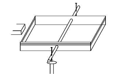
Fig. 1
We create the scale from a rectangular piece of cardboard (fig. 1). It can be about 20 – 30 cm long, and approximately 10 cm wide. We bend the long edges into a 90° angle, about 2cm wide, creating a small “trough”. We make a hole in the middle of the newly created walls and pull a wooden skewer through. Pierce a pin through each side of the scale so that the pins are parallel to each other. These will serve as the fulcrum of our scale. The pins will be put on the heads of two nails hammered into a piece of wood. It is better to use large flat headed nails.
By moving the nails deeper into the skewer, we can change the sensitivity of our scale. One might discuss how the pin position affects the sensitivity of the scale, why the scale topples to one side or the other and doesn’t stay in the balanced position when the pins are too high, we could calculate, how far under the pins the centre of gravity is, etc. The construction of this measuring instrument can be used to really deepen one’s knowledge of the relevant parts of physics.
Affixing the position of the pins inside the skewer with a droplet of rosin, which is used in soldering, has proven efficient. It can be applied by a soldering gun and, if necessary, the rosin can be reheated and the pins shifted. A third pin in the skewer will work as our pointer, indicating the position of equilibrium (the pin will point DOWNWARDS toward a point made on the piece of wood). We can try that by turning the skewer towards the carton, the balance can be “fine-tuned”, because the point of contact with the nails shifts together with the turning of the carton. We can engage the pupils in a discussion about the influence of the point of contact on the sensitivity of our scale.
So far we’ve created a normal balance scale. This can be used by students to weigh light objects, with around 0.1 gram accuracy. The counterweight can be made from normal typing paper. If the grammage of the paper is 80g/m2, then 1 m2 weighs 80 grams. Therefore 12.5cm2 weighs exactly 0.1 grams.
To determine the magnetic force acting on a conductor, we coil the wire around the scale – around the sides, parallel to the “base” of the scale. We can use almost any kind of enamelled copper wire (the only parameter is that it can’t be too thin), or a thinner bell wire. We used 10 turns for our coil; more turns would mean higher measuring sensitivity.
Current will be supplied by a battery placed on the scale (on the cardboard base). In the prototype, 2 AA batteries in series were sufficient. They were put in a battery holder commonly sold in electronics stores (a holder with two outgoing sockets is more appropriate). The power source is the heaviest part of our scale and therefore must be placed directly beneath the skewer, on the axis of the scale. The easiest way to hold the holder in place is to squeeze it between the cardboard base and the skewer. We can roughly tune the balance of the scale by shifting the battery holder.
The current will not be supplied directly from the power source to the wire, but we will use a 3.5V, 0.2-0.3A light bulb, which we will also place on the axis of our scale, e.g. on the side. The light bulb will reduce the current and enable us to estimate the current’s size accurately enough, so we do not need an ammeter. By screwing the light bulb in or out, it can also be used as a switch.
There are many ways of modifying the construction described here (e.g. making the scale base from polystyrene/styrofoam instead of cardboard, changing the number of turns on the coil, hanging the scale on strings etc.).
The magnet, the magnetic induction of which we wish to measure, will be moved from the side to the shorter side of the scale. We have to multiply the force acting upon the conductor F = BIl by the number of turns n
The biggest hurdle is the length l, which is quite difficult to determine. Magnetic induction is actually different in different places, so the best way to measure the force is through the integration along the wire (furthermore, the force acts upon the longer sides of the scale as well, so we should integrate not the force, but the moment of force in relation to the scale’s axis). It is therefore clear, that our scale is only able of showing the “average”, or more precisely a characteristic value of magnetic induction B. If we hold a bar magnet very close to the coil, we can say that l is the width of the magnet. If we hold the magnet a little further away, we can imagine that the magnetic field lines “hit” a longer portion of the conductor and l is therefore bigger.
The measuring itself is based on the fact that the scale tilts to one side. If the balance is restored by an object with weight m (e.g. a piece of typing paper) laid down on the other side of the scale, BIln = mg, with g being gravitational acceleration. The measured B is therefore \[ B= \frac{mg}{nIl} .\]
If we do not put the counterweight to the edge of the scale, we must add the distance ratio to our equation. The magnitude of B, measurable by our scale, will be estimated from the typical values m = 0.1 g, g = 10 m/s2, I = 0.2 A, l = 2.5 cm, n = 10 and B = 20 mT. That is the magnitude of the magnetic induction close to a typical school bar magnet. The sensitivity of the scale can be set so that it shows even much smaller forces. Our scale can therefore measure B down several milliteslas and even less (if we put more turns on a coil).
Our measurements are only approximate. By comparing our results with a Tesla meter we can see that the deviation can be more than 50 %. The measurement is, however, very visual (no “black boxes” involved), it clearly illustrates the acting of a magnetic field upon a wire with current flowing through and helps students make a clear picture about the intensity of magnetic induction available in most commercially sold magnets. That is why I think that such a simple tool and its construction can find their place directly in physics class or in various non-mandatory courses, classes, etc.
“Panel” voltmeter with LED
The following project can help students understand how a voltage divider made out of two resistors works.
The LED starts shining from around 1.7 to 1.8 V (red diode), or up to 2 V (green). Let’s use a green diode in our experiment and let’s assume it starts emitting light at the precise voltage of 2 V. With the lower voltage the diode does not emit light and does not draw practically any current.
Fig. 2
If the resistors are connected like in the picture and their resistance is the same, R1 = R2, voltage lower than 4 V is divided in half and the diode does not shine. It starts shining when voltage of the circuit U is higher than 4 volts.
By choosing a certain ratio of R2/(R1+R2), we can set the threshold, at which the diode starts to shine. And right here we have a topic for a small “team project”: Groups of student or pupils will create their own “measuring unit” – with various values of voltage U at which the diode starts to shine (3V, 4V, 5V, ...). If we connect all these units in parallel, we get a simple voltmeter, which will indicate the voltage with the number of shining diodes.
The practical construction can use the technology shown at the last Physics teachers’ inventions fair: soldering components onto small brass nails hammered into pieces of wood. This way, pupils have the opportunity to get better at soldering as well (honestly said, many future physics teachers were happy to train their soldering skills. At the time of the project they were 2nd year students. It should be said that some were soldering for the first time in their lives). The pieces of wood can then be connected to a linked panel, so the resulting measuring tool is truly “panel”.
However, the measuring accuracy is in no way astonishing. The exceeding of the set voltage is not indicated by a sudden strong glow of the LED; a few tenths of a volt above the set voltage the glow is still relatively weak. But differences of around .25 V can be distinguished quite reliably. Our voltmeter also consumes a considerable amount of energy. This depends on the values of the resistors. It is good to choose the resistance of R1 around 220 Ω - think from 150 Ω to 270 Ω. Higher values mean dimmer shine, Loir values, on the other hand, mean higher energy consumption and possibly overloading the LEDs by higher current.
The created voltmeter is therefore unsuited for routine measurements. However, during the construction, students and pupils can think about and try not only the principles of the voltage divider, but also connecting resistors in series and in parallel. To have an exact ratio of resistances in our divider, commercially available resistors are no longer sufficient, and it is necessary to combine them appropriately. Pupils will also learn to pay attention to the polarity of an LED and they will practice their soldering skills as well.
Even this construction can be modified and presented as a question. For example: How can this construction be set up to make the diode shine from 1 V? (Hint: We would need e.g. an AA battery 1.5V. If connected in series…) Or: How could we achieve the effect of the diode lighting up at the voltage of 3V and stop shining at 4V? (That would be a little more complex and this set-up would require e.g. one transistor…) Would it be possible to make the diode suddenly light up at full shine when the voltage is higher than a selected threshold? But this would be perhaps too far into the field of electronics…
Automatic scale A.K.A. the see-saw tractor
The last instrument is probably “the most unconventional”. It exemplifies the principle of the balance of a lever (or the fact that for the moments of force must equal zero for the object to be balanced, if you will).
The base of the tool is a two-arm lever, a see-saw of sorts – it could be a longer flat piece of wood supported in the middle. We put the object we want to measure on one end of the see-saw. The automatic balancing process is provided by a little “tractor” on the other side of the lever; it is constructed to always ride uphill.
The function of this “auto-scale” is obvious. Let the tractor and the weighed object be the same distance from the axis. If the tractor is heavier than said object, the scale topples to the side of the tractor. Therefore, the tractor will move uphill – until the moments of force equal each other, or rather until the object in question outweighs the scale. From the thus created position of the tractor (and its weight) the weight of the weighed object can be easily calculated. We might even draw a scale on the arm where the tractor is and equip the tractor with a needle pointing to the scale… ingenuity knows no bounds.
If the scale is constructed from a piece of wood like in the picture, the tractor will actually start moving backwards when the scale topples to the object’s side, then forwards again, then backwards again – “oscillating” around the balanced position. Pupils can answer questions as to why this phenomenon occurs, how it relates to the centre of gravity of the construction, how this construction can be modified to make the weighing process more accurate etc.
The author constructed the scale using a piece of polystyrene supported by two laths, which were able to rotate around the horizontal axis. The “tractor” was made from Merkur (a metal construction toy). There are spindles, wheels, tracks, worm gears and in one variation of Merkur labeled “Motors”, we can find a suitable spindle-equipped motor. The tractor can work with just one D-cell battery, but to ensure reliable uphill motion, it is recommended to use two D-cells in series. The switching of battery polarity is fairly simple as well, and it will make the tractor drive always uphill. In the construction described the D-cell was suspended from two strings with the terminals pointing downwards, so that it could swing freely. If the tractor is tilted, the terminals touch one of the two pairs of wires, connected to the motor. One of the two pairs is simply interchanged to move the tractor backwards. After all, designing a polarity switch could be a good side project…
The “auto-scale” can surely be modified in many ways, use your imagination. They almost surely are not useful for day-to-day weighing. They are too rough and slow to serve that purpose. But someone might find this instrument useful for understanding the principle of balance on a lever and the scale can liven up the physics class…